00 Why?
I always come back to the Super Nintendo (SNES). It was my first console and it's still my most potent source of nostalgia. It inspired my early interest in electronics as a teenager, designing circuits for mods and flash carts that I hoped to build one day. I followed the launch of Hackaday, Adafruit, and the progress of bunnie Huang's Chumby and knew exactly what I wanted to do.
I dropped out of my final years of high school to study hands-on electronics at college, and continued on to university. Then, finally equipped with those skills I'd aspired to, I went off-track and spent the next fifteen years working in data, ML and software. A lot has changed in that time but I'm back now, picking up exactly where I left off.
The Super Network Adapter is an exercise in '16-bit futurism', it aims to be a faithful peripheral to the original SNES hardware and what we imagined the future might be back then: a wireless link to the net, sync'ing saves across devices and an uplink to AI.
01 Prototyping
The SNES never had a dedicated network port. The closest it came was the Satellaview, a modem peripheral connected to a hidden expansion port that could receive game broadcasts via satellite. There was also the XBAND, a modem that plugged into the cartridge slot and supported pass-through patching of specific games for online play. Reproducing the hardware of either of these today would be challenging, however most peripherals for the SNES took a much simpler route, they used one of the controller ports.
Controller Serial Link
The SNES controller ports are small synchronous serial buses that a game can control, setting and reading individual lines and driving the clock. These ports have seven lines but in a typical controller cable, only five tend to be present, with the wires for D1 and IOBit left out. To make sourcing parts for this project easier, my design also only relies on the remaining five wires.
 ┌─────────────────────────────────────────────────────────────╮
 │ ┌──────────────────────────────┐  ┌───────────────────────╮ │
 │ │  ●       ●       ●       ●   │  │   ●       ●       ●   │ │
 │ └──────────────────────────────┘  └───────────────────────╯ │
 └─────────────────────────────────────────────────────────────╯
      1       2       3       4          5       6       7
      5v     CLK    Latch     D0         D1    IOBit    GND
First I needed a protocol for talking over this serial link, which I iterated with Mesen and a virtual network adapter written in Lua simulating the controller port link. This protocol has the SNES writing to the Latch line and reading from the adapter on D0, one bit at a time ('bit-banging'). Even with some optimisation (unrolling loops and ignoring mid-stream replies) this approach tops out at about 30 KB/s, but that's enough for the '90s.
Breadboard Version
The first physical prototype was built using a Pico 2 W dev board. The additional circuitry needed was very simple, just some pull-up resistors for CLK and Latch. The board's RP2350A can handle the console's 5v logic on its pins directly, and it has two cores: one can maintain the console link, while the other maintains the Wi-Fi network link, without juggling interrupts.
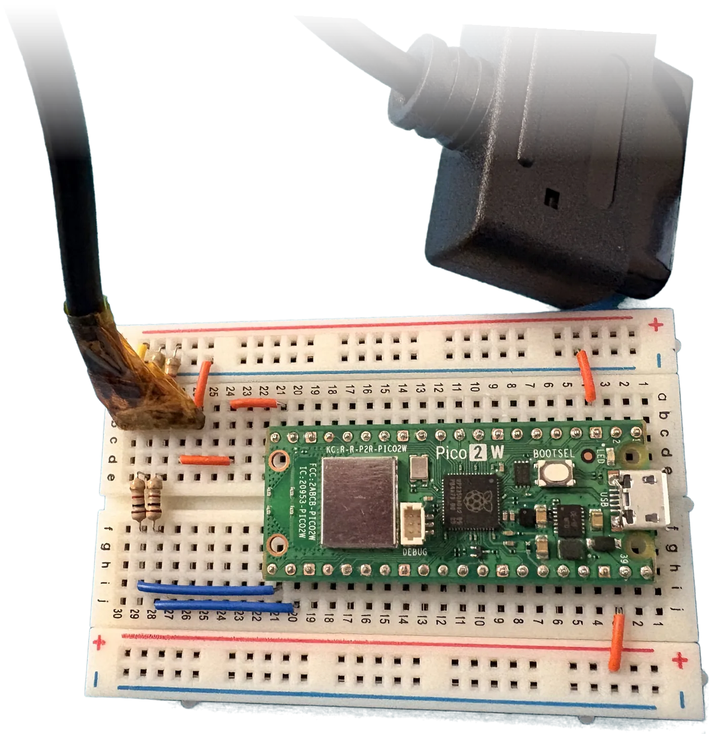
Controller port pinout
| Pin | Signal | Wiring |
|---|---|---|
| 1 | +5V | feeds pull-ups only (Pico on USB supply for now) |
| 2 | CLK | GPIO pin and 4k7 pull-up |
| 3 | Latch | GPIO pin and 4k7 pull-up |
| 4 | D0 | GPIO pin, open drain |
| 7 | GND | Shared GND |
The prototype runs from USB, with the console's 5v only feeding the pull-ups. I did not connect the SNES 5v to the Pico's VBUS or VSYS while USB is plugged in. The Pico was powered on before the console so the RP2350's pins were ready to handle 5v. The PCB design later can run on either supply.
02 Save sync
Adding Cloud Save or 'Save Sync' seemed the most practical use for a Wi-Fi connection. I often go back to the SNES and start a new game, but if I could continue playing that save file in RetroArch on my phone and then back to the SNES, it would fit into my life much more easily.
Game save data is stored in battery-backed SRAM and in order for a game to send that through my adapter, I needed some of my own code to run. I already have a programmable flash cart for the SNES, so I wrote a utility to patch ROMs and inject this 'save sync' code into the reset vector. At power-on and whenever the console is reset, it syncs the save data through the adapter to a WebDAV server as saves/<core>/<name>.srm (the same path RetroArch uses) so the console save can be continued on the phone, and vice versa.
Joining Wi-Fi
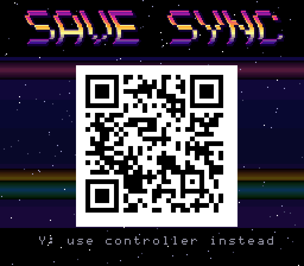
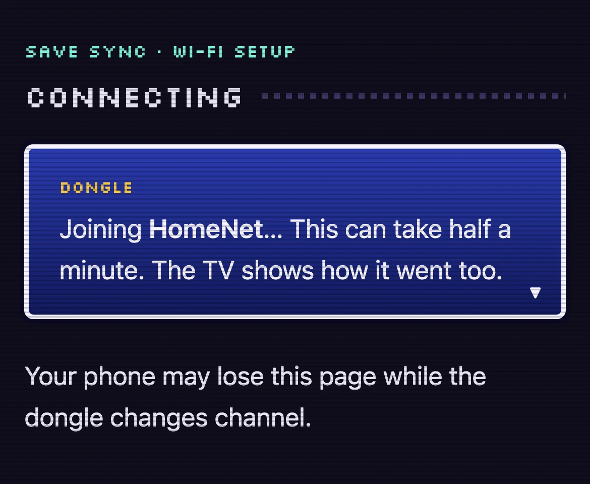
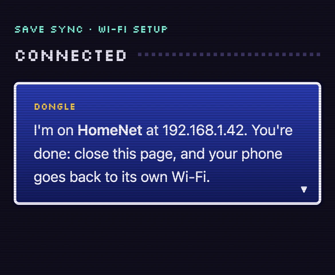
First though, the adapter needs to join the local Wi-Fi network. I wanted an era-appropriate UI that can be run from a setup ROM (fig.2), which has you pick a network and type its password with an on-screen keyboard, one letter at a time. That felt most 'authentic' but I also made a second iteration that shows the typical QR code on the TV for setup via mobile phone.
The second version has the adapter set up a temporary network. Scanning the QR code with a phone joins the network and it then does the usual captive portal flow to open the adapter's setup page, where the network and WebDAV auth details can be input in a much more user-friendly way.
Pushing and Pulling Saves
An important detail to get right was checking whether the save on the cartridge was newest, or whether to download a newer one from WebDAV. RetroArch keeps a manifest file with a hash of every save, so the adapter updates that too, comparing hashes to decide whether the cartridge or the server has the newest save. If both sides have changed, nothing is overwritten and the cartridge's save goes to a conflicts folder to play it safe.
SRAM saves are small but this sync still has to run whenever a game starts, potentially introducing a delay. To avoid this, the save is split into chunks that each have their own checksum, so only the chunks that have changed are sent over the controller port. In practice this makes the save sync delay imperceptible, and only when an existing save is pulled by the SNES for the first time is there a 1-2s load screen.
03 AI dialogue
Naturally in 2026, an internet connection also means a connection to LLMs. The dialogue in SNES-era games tends to be fixed and unresponsive. In A Link to the Past, the villagers don't react when you smash their pots (unlike in subsequent Zelda games). With the network adapter though, we can hook the game's dialogue text renderer to swap out the original text for an in-character line generated by an LLM.

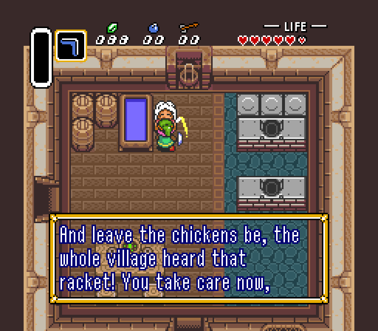
In order to prompt for dialogue, the LLM needs to be passed the game context, such as the character being interacted with and recent events. Since Link to the Past has been fully disassembled, it was possible to patch it to accumulate this state in RAM and push it out over the controller serial to the adapter and on to an LLM. In order to avoid game-breaking delays in LLM response times, I switched to speculatively generating the dialogue when Link approaches an NPC, storing the responses in a cache and invalidating them as the context updates. This is a great way to burn tokens so probably not something to do for the full game duration!
04 Hardware
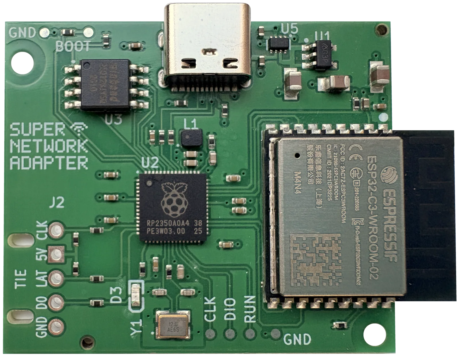
When designing the PCB version of the adapter (fig.0) I replicated the same architecture as the prototype, an RP2350A microcontroller that handles the 5v lines and maintains the serial link, with an ESP32-C3 Wi-Fi coprocessor that handles the Wi-Fi connection. These communicate with each other over UART, allowing each link to be maintained by a dedicated core.
┌─────────┐ port 2 ┌─────────┐ uart ┌──────────┐ wi-fi ┌────────┐
│ SNES    │──────▸ │ RP2350A │────▸ │ ESP32-C3 │~~~~~▸ │ cloud  │
│ 65816   │◂────── │ PIO     │◂──── │ TCP/TLS  │◂~~~~~ │ WebDAV │
└─────────┘        └─────────┘      └──────────┘       └────────┘
  3.58 MHz           150 MHz          160 MHz
A PIO state machine on the RP2350 watches clock and latch, queueing the data and filtering out glitches shorter than 100 ns. This frees up the cores to prepare data to be sent over D0 while also talking to the C3.
The USB socket was included not just for flashing the board but also to support debugging it while it is powered from the SNES. This means the board needs to safely support taking a 5v supply from either the controller port or USB, and avoid backfeeding if both are connected. This is done with a LM66200 dual ideal diode. Supply can be taken from either source and we avoid the voltage drop that would come with using actual diodes. I'd seen some brownouts in tests on the breadboard, so designed the PCB with plenty of headroom for the LDO regulator even if the supply rail sags on a Wi-Fi burst.
While prototyping I also had issues when using series resistors on the link lines. This may be related to erratum RP2350-E9 in the A2 revision (stepping) of the RP2350A on my Pico 2 W. In the assembled PCB order I switched these to 0 Ω links, as they're just for protection and I wasn't sure which stepping the PCB would be assembled with. The boards turned out to have the fixed A4 stepping, so real resistors can go in next time.
05 Enclosure
The case is just a tray and a lid that sandwich the PCB, though I did want it to nod toward an era-appropriate design language. It was generated in code (build123d) using the PCB's STEP files from KiCad, so that the design could be tested within a single 3D model.
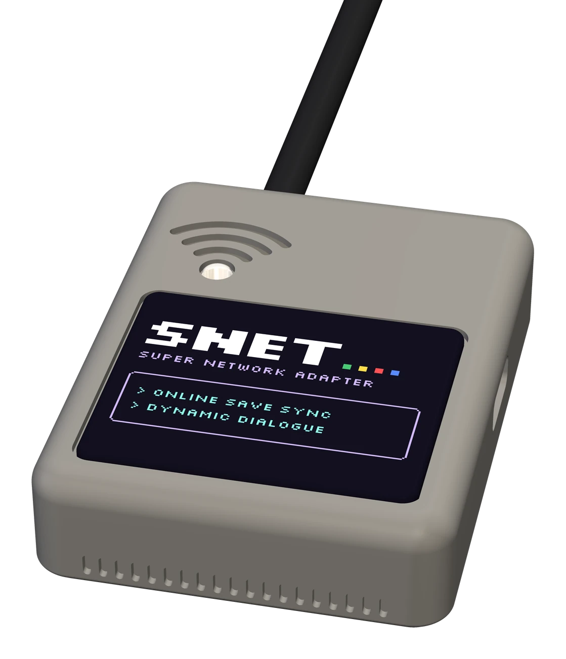
The two halves join around the cable and the USB socket, and there are M2 pillars that align with the drilled holes in the PCB to hold everything together.
Since the PCB has a status LED, this design has a light pipe that channels that light up to become the dot of the etched Wi-Fi icon. It's not the prettiest of designs, but I thought that was cute.
I've ordered a batch of these enclosures to be 3D printed and will update with actual photos once they arrive and the adapter is fully assembled.
06 Build log
- 65816 toolchain, headless emulator tests
- Breadboard link to port 2 working
- First save uploaded from the console
- PCB designed and ordered from JLCPCB
- PCBs arrive and work perfectly!
- Ordered 3D printed enclosures
- Awaiting delivery of enclosures